| What?......Are
you CRAZY? |
| |

|
2/23/02 We have decided to
replace the helm! The new helm will be the Edson CD-i Pedestal Below
Deck Helm. This project is a bit extreme, but it is my favorite
upgrade project. The goal....to get rid of the steering wheel axle
that
needs to be straddled at the helm.
The Edson Helm CD-i Literature. PDF doc.
(106K) |
| |

|
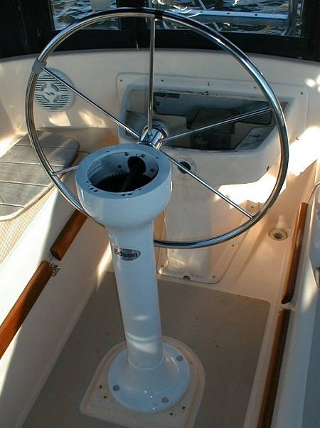
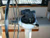
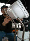
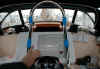
2/23/02 Original helm
engine controls, these will be replaced with a Edson Panish single lever engine
control.
|
| |

|
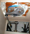
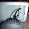
2/23/02 The original rack and
pinion gear that was under the helm seat. This will be removed.
 This really seems like a weak design. The entire force of the helm
is transferred to this thin shell of fiberglass where the aluminum plate
is bolted.
This really seems like a weak design. The entire force of the helm
is transferred to this thin shell of fiberglass where the aluminum plate
is bolted. |
| |
 |
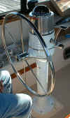
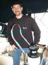
2/23/02 Another view of the
original helm with an Autohelm 4000. |
| The
Study Begins... |
| |

|
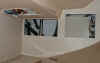
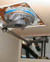
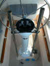
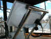
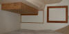
2/23/02 This is the bottom of the
helm where the headliner is dropped to allow for the helm bolts and cable
runs.
 This will be cut away and the below deck parts will be boxed in.
 |
| |
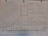 |
2/23/02 Sketch / Cross
Section study of the deck and how the new helm will fit under the
headliner. |
| We
Commit....Edson will make it work! |
| |
 |
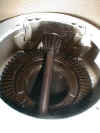
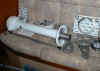
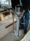
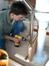
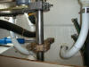
3/9/02 This is the access
hole we cut to gain access to the rudder post. We will need to mount an
8" arm to the rudder which will be driven by the drag link arm from
the new helm. |
| |
 |
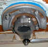
3/9/02 The bottom of the
old
helm with the through deck bolts looking aft at the rudder post. |
| |
 |
3/9/02 Looking at the helm
from the side, showing the rudder post and deck. |
| |
 |
3/9/02 A close up of the
deck where the helm will bolt down. This deck will be reinforced with
plywood and fiberglass. |
| Remove
the Old Helm |
| |
 |
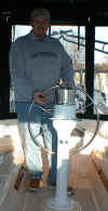
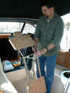
3/16/02 What to do
with your OLD HELM....Hey this works!
 |
| |
 |
3/16/02 The helm
is REMOVED.

 |
| The
New Helm Arrives |
| |
 |
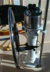
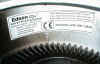
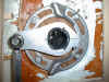
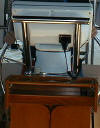
3/16/02 The Edson
CD-i Helm. This is the output arm which will be below the deck. Notice
the tube that is keyed and will drive the output arm. |
| |
 |
3/16/02 The top of
the helm integrates the gear with the wheel shaft. This photo shows
the steering wheel shaft that will drive the output arm.
 The helm specs and allowed forces...
 Another view of the top of the pedestal.
 |
| |
 |
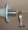
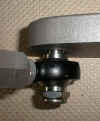
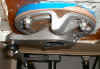
3/16/02 The output
arm, rudder post arm, and the stop ring.
 The solid rod between the arms.
 |
| |
 |
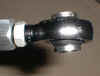
3/16/02 The ball
joint
 |
| |
 |
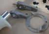
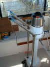
3/16/02 The Edson CD-i
Helm ready to go.....
 |
| Installation
is a SUCCESS ! |
| |
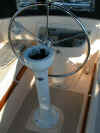 |
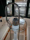
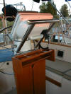
3/23/02 The Edson CD-i
is INSTALLED. Mission accomplished! What a beautiful piece of
machinery, engineering and design. I am very impressed with this design.
Edson, this is a great product!
 |
| |
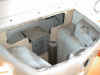 |
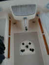
3/23/02 The view of the
seat with the old rack and pinion removed. This will allow for an
emergency tiller drop on if the need should every arise.
No going back now! This is IT.
|
| New
Panish / Edson Engine Controls |
| |
 |
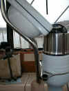
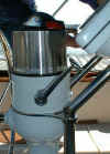
3/23/02 The Panish
Single Lever Engine Control is bolted to the top of the CD-i. This
single lever will shift and control the throttle.


 |
| |
 |
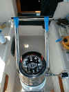
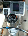
3/23/02 The Compass
is bolted on top of the engine control. We need to add the pedestal guard
this week.

 |
| I
Love it |
| |
 |
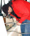
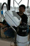
3/23/02 Hayden
with the NEW EDSON HELM.
I first learned of this helm at the Annapolis Boat Show,
and I really thought it was a great idea. As we planned our upgrades, I
insisted on this new helm......well Radeen insisted on Boat Beds.....so
now we both are elated with the upgrades. |
| The
Below Deck Gear of the Edson CD-i |
| |
 |
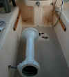
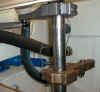
3/23/02 Below the
deck is 6" output lever pushing a solid draglink with ball joints
and an 8" tiller arm bolted to the 2" rudder post. Notice
the integrated stop ring.
 |
| |
 |
3/23/02 Close up
of the 6" output arm and how it is driven by the integrated
torque tube that is inside the pedestal. This also shows the 3/4"
marine plywood that was epoxied to the bottom of the deck for added
strength. (the blue tape was to keep the epoxy from running) |
| |
 |
3/23/02 The integrated
Stop Ring is adjustable and can be rotated and adjusted for perfect
alignment. |
| |
 |
3/23/02 The shift
and throttle cables along with compass wiring will run up the center
of the torque tube. Black rubber padding is factory installed to prevent
cable abrasion. |
| |
 |
3/23/02 The rudder
post with the helm tiller arm and the B & G tiller arm. These arms
will be through bolted to the rudder post after all the alignments are
complete. |
| Old
VS NEW |
| |
|
3/23/02 One More
Look at the CD-i
the old helm....
|
| The
Pedestal Guard |
| |
 |
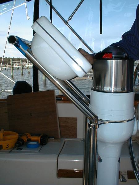
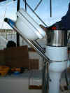
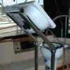
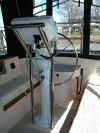
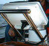
3/28/02 OOPS...The
Edson 2 bend pedestal guard did not work with the new helm and a
NavPod housing unit. The
new Panish engine control raises the compass too high and it hits the
NavPod unit. This photo shows the conflict and you can see that the guard is
NOT even in the mount. Edson does not recommend mounting Radar on this
slopped surface.

 |
| |
 |
3/28/02 OK....Let's
Make It Work! This guard is holding up the install of the instruments,
pilot head, VHF, windlass switch. WE NEED TO FIX THIS!
So we take a tubing cutter to it. We think we can
rearrange the unit and Tig weld it back together in a usable
configuration. |
| |
 |
3/28/02 The solution
looks like this. It will require Rob to weld the unit, but it seems
like a viable solution. |
| |
 |
3/28/02 Rob Glebe and
I get a working solution that will allow the NavPod to slide back
from the compass. This shot is for Edson; we will send the dimensions to
them. |
| |
 |
3/28/02 The new
test assembly and study of the new pedestal shape.

 The issue now is.....How do you get your compass light out when you
need to replace the bulb?
The issue now is.....How do you get your compass light out when you
need to replace the bulb? |
| The
Visibility Issue....What can I see from the Helm? |
| |
 |
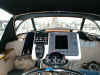
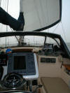
3/28/02 What I can
see from the helm......NOTHING! This is unacceptable for the helm;
this photo shows my view. Radeen's view is 4" to 6" lower, so it
would be worse. |
| |
 |
3/28/02 What I
want to see from the helm. So.....back to the drawing board we go.
Let's start over! The issues are: 1. The helm is getting too high. 2. The
1" tubing is too small for radar and other wires. 3. The Edson helm
with the Panish engine control places the compass higher. 4. The NavPod
needs to be held behind the compass. |
| |
 |
3/28/02 The radar
wiring is causing an issue. The 1" tubing is too small for radar,
power, pilot, and VHF wiring. Look at these wires for just one tube! |
| We
Design Our Own Pedestal Guard |
| |
 |
 3/30/02
Rob Glebe is a WELDER.....we went to Kato Marine in Annapolis and
picked up some 1 1/4" SS 304 tubing. We designed the 45 degree slope
and Rob welded them together. 3/30/02
Rob Glebe is a WELDER.....we went to Kato Marine in Annapolis and
picked up some 1 1/4" SS 304 tubing. We designed the 45 degree slope
and Rob welded them together.
|
| |
 |
3/30/02 A Saddle
cut was milled into the side tubes to allow for the top handle to nest
into the section of the tube. The ends will be finished off with a Teak
carved Rosetta.
The Goal: To lower the radar to behind the
compass allowing for visibility from the helm. |
| |
 |
3/30/02 The view
from the helm.....looks good.

 The shifter lever is a factor
 |
| |
 |
3/30/02 The NavPod
on the custom pedestal.

The pedestal feet needed to be milled with an 1 1/4" end mill.
Rob re-worked these back in the shop on the milling machine. |
| |
 |
3/30/02 After fitting
in place, the pedestal was bolted together and removed to be taken
back to Rob's welding shop. This way there could be no problem with the
unit fitting the Edson guard and feet.
|
| |
 |
3/30/02 The guard
removed, and on its way to the welding and polishing shop. I must say,
Rob Glebe is a real craftsman. |
| |
|
4/2/02.....Rob
Called.....the pedestal guard is in...
and looks great!
|
| |
 |
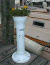
4/6/02 The custom
pedestal of 1 1/4" SS tubing with a handle. |
| |
 |
4/6/02 The bottom of
the NavPod has a down light and a plug for the RAM VHF mic.
 |
| |
 |
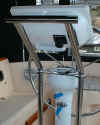
4/6/02 The completed
NavPod with color radar, B & G pilot, and VHF RAM mic.
 The shifter lever and compass limited the position of the
NavPod.
The shifter lever and compass limited the position of the
NavPod. |
| |
 |
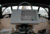
4/6/02 THE VIEW
FROM THE HELM. GREAT! This was a primary goal, to be able to see over
the pod when seated. This is my view without sitting on a cushion. IT ALL
WORKED OUT! We are very happy with this design. |
| |
The new CD-i |
4/6/02 Thank you EDSON....THANK
YOU ROB GLEBE!
The old helm... |
| |
! |
Conclusion:
(4/6/02) This was a much bigger job then first anticipated, and the problems with
the pedestal were unforeseen. The below decks levers and output arm worked
out great, and the Edson CD-i bolted right in place. Outstanding design
work by the Edson team! The cutout we made in the stern is a MUST to have
access to the rudder post for drilling and mounting of the rudder arms.
The wiring running from the radar, lights, pilot, and VHF demanded the use
of 1 1/4" tubing. Even with that, it was still a very tight wiring
run. And finally, you need a craftsman like Rob Glebe to make a difficult
design like this all work out. Rob was patient and determined to make this
install work out perfectly. Rob is an unbelievable craftsman. His work is
the best in the industry. As far as I know, this is the first Edson CD-i
helm replacing an existing helm. Now for some OCEAN Test! |
|
Finishing touches... |
| |
 |
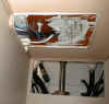
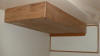
The teak helm
enclosure and the stern cutout enclosure. The stern piece is 1/2" ply with
almond Formica laminate and teak trim. The board is surface mounted just
like the water heater cover. |
| |
 |
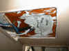
Close up... |
| |
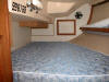 |
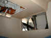
A view of the entire
cabin. The dropped teak box does not effect this cabin very much. |
| |
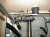 |
Rudder reference
mounted to the ceiling, and enclosed in a teak box. |
| |
 |
New cockpit drain
hoses were easy to replace now that we had this access panel cut in the
stern. This access panel is a must! |
| |
 |
WOW, look at the view
from the helm in a seated position. GOAL ACCOMPLISHED! I can see over the
radar and out the dodger. |
| |
 |
Brass fittings cap
the end of the stainless steel handhold. A teak table and upholder were also
added. |
| |
 |
Helm table and cup
holder. The cup holder is removable since the table hinges up and would make
the cup holder hit the 45 degree radar mount. Notice
the down light mounted on the backside of the radar mount. White. |
| |
 |
Close up, brass end
caps, radar mount on 45 degrees behind compass and low, RAM mic plug, down
light, and hidden on the bottom are 2 extra 12 volt plugs. |
| |
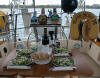 |
Hah...dinner in the
cockpit while anchored in salt pond, Block Island, RI summer 2002.
Life is good. |
| |
! |
Conclusion #2
(12/27/02)
After using this new helm for the first season in 2002 we have discover
these wonderful issues. 1.) With the same wheel but with the wheel moved up
higher, you can move into and out of the helm area with your legs fitting
between the seats and the pedestal. This was not possible before. Most IPs
your leg will not fit between the seat and the wheel, you have to step up on
the set and then into the helm area. 2.) This radar location AT THE HELM is
the only way to go. We had great debates on the discussion board about
screen location. We have a cockpit enclosure, so sitting back here at the
helm is not an issue. We used the radar 100% and loved it at the helm. I
would never want it where I can not reach it while driving the boat. 3.)
This Edson CD-i helm is a wonderful piece of engineering and design. I have
no worries about the refit. 4.) The Panish single lever engine control is
great. We had to do a lot of work to make it shift the KBW10 trans, but that
is another full story. |